VII/C Drivetrain Configurations
VII/C Propulsion Drive System
In this blog post, we will review all of the different components and configurations available to a VII/C Uboat.
Propellers
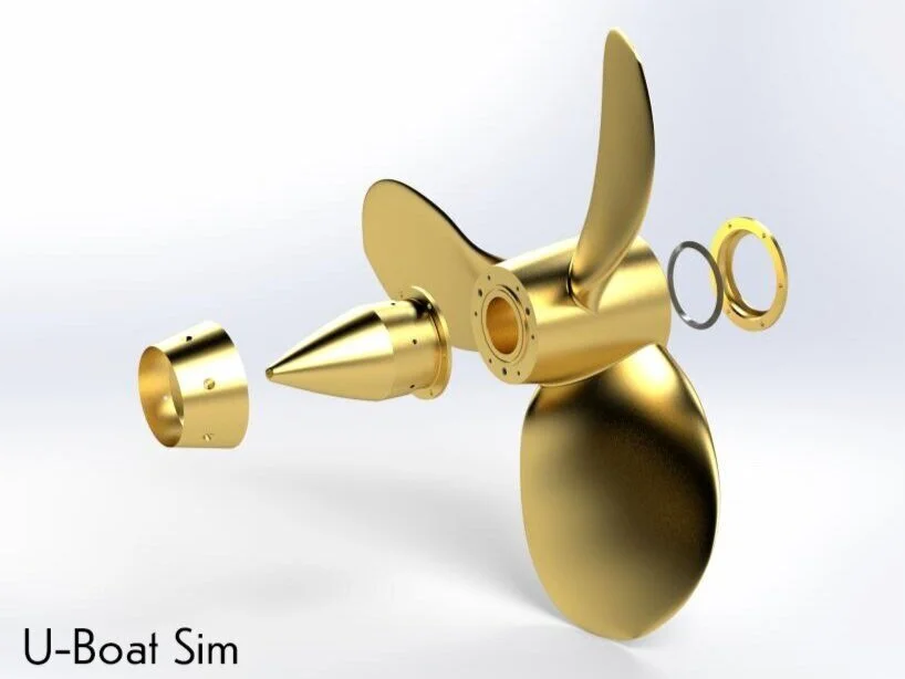
The VII/C U-Boat is driven by two 3-bladed 85cm diameter propellers. The propellers are counter rotating, with the port propeller rotating counter-clockwise and the starboard propeller rotating clockwise.
Thrust Block
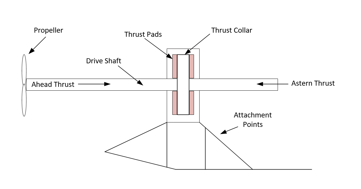
As the propellers turn, they push against the water and generate forward and reverse thrust (depending on the axial rotation direction of the propeller). The pushing forces applied to the propeller drive shaft by the propellers are so great, they would easily rip the electric and diesel motors from their attachments to the U-Boat hull. To prevent this from occurring and to ensure the thrust forces are properly applied to the U-Boat’s hull, thrust blocks are used.
A trust block is an arrangement of components which absorb the thrust forces developed by the rotating propellers and distributes them to the U-Boat structure. As the drive shaft is pushed ahead or astern by the thrust forces, an integrated thrust collar pushes against the ahead or astern thrust pads. The thrust pads absorb the forces and distribute them to the U-Boat via the thrust block attachment points.
The thrust block assembly submerges the thrust collar and thrust pads in oil and features a water cooling jacket to absorb the heat generated by the trust collar / thrust pad friction. Each thrust block is able to transfer up to 10,000 kg of thrust.
On the VII/C, Michell thrust bearings were used. These bearing house the thrust pads which have wedge-shaped sliding surfaces and ridges in the direction of the thrust collar. As the thrust collar pushes against the pads, the shape and ridges in the pads create an oil film to reduce friction and transfer the trust to the bearings.
Shaft Brake
The shaft brake is a differential band brake which is driven by a lead bolt. It affects the shaft drum behind the flange couple and is designed to hold the propeller shaft from spinning when the E-Motor main clutch is disengaged.
This would prevent the propeller shaft from spinning when the the opposite propeller was spinning.
E-Motor Main Clutch
The main propeller shaft is connected to the electric motor shaft via a mechanical clutch. This main clutch is a double cone friction type clutch which allows small axial shifts in between the two shafts. This clutch can transfer a maximum of 4,400 m/kg (30,800 ft/lbs) of torque.
Diesel Engine Clutch
The diesel engine clutch is constructed in the same way as the main clutch and allows for the disengagement of the diesel engine from the electric engine shaft. The engagement / disengagement is executed via a piston ram which is operated with compressed air and oil. In case of piston ram failure, there is a manual hand operation wheel that can be turned to operate the clutch. This clutch could transfer a maximum of 8,800 m/kg (61,600 ft/lbs) of torque.
Drivetrain Operating Modes
Diesel engine only drive
In diesel engine only drive, both diesels would be engaged to the propeller shafts via the main clutches and diesel engine clutches. The electric motors would be unpowered and would be spun by the axial rotation of the electric motor shafts.
Electric motor only drive
In electric motor only drive, the diesel engine clutch would be unclutched and the diesels would be turned off. The electric motors would be powered by the batteries and would drive the propeller shafts via the engaged main clutches.
Support and buffer Mode
In support mode the power output of the diesel engine would be increased by applying power to the electric motors. The propeller shaft would be spun by both the diesel engine via the main diesel clutch, as well as the electric motor on the same drive shaft.
Buffer mode would be mainly used in rough seas to help stabilize the propeller RPM. The diesel engine would spin the main propeller shaft as in Diesel engine only drive mode, but the electric motor voltage would be adjusted so that it would attempt to maintain a set RPM on the shaft. If the propeller would unintentionally run above the surface of the water due to rough seas, the electric motor switch to generator mode and place load on the shaft ensuring the diesel RPM would not reach dangerous levels.
Together the support and buffer would allow the electric motors to apply extra power to the shaft to increase RPM while applying load to the shaft to prevent unsafe RPM levels when the propellers would breach the surface of the water.
Charging modes
Charging while on the surface with one diesel powering a propeller and the other diesel powering only the electric motor as a generator (no propeller drive on the charging side, high current charging mode).
Charging while on the surface with both diesel engines driving the propeller as well as both electric motors in generator mode (limited current charging mode)
Charging configurations
Because of the design of the powertrain, many different charging configurations where possible. These include:
1 diesel driving propeller, the other diesel driving electric motor in high current charge mode
1 diesel driving propeller and electric motor, the other electric motor driving propeller with diesel off (no charging, all power generated by one motor would feed the other driving the propeller)
1 diesel driving propeller, the other diesel driving propeller and electric motor in low current charging mode
2 diesels driving electric motors as generators and propellers in low current charging mode
2 diesels driving propellers and electric motors idle (normal diesel engine only configuration)
2 diesels driving propellers plus both electric motors driving propellers (support and buffer mode)


